Merit of the Technology
Thrust 1 | Thrust 2 |
Thrust 3 | Thrust 4 |
Thrust 5
Thrust 1: Flexible Piezo Paint
Sensing Dot Array (Sensor Technology)
The paint sensor offers the unique blending of the high piezo properties of ferroelectric ceramics (e.g., PZT) and the mechanical flexibility and formability of polymer (e.g., PVDF).
The advantage of piezo paint is that, if well designed, the sensor will exhibit the best qualities of each constituent and offers some parameters that neither constituent possesses.
 |
|
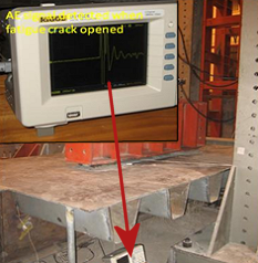
Fig. 1: AE signal detected when fatigue
crack
opened in a fatigue testing of steel
orthortropic deck. |
|
Challenge: The feasibility of using flexible piezo paint for wideband AE signal sensing has been experimentally demonstrated, but comprehensive research is needed to fully characterize the sensing performance of piezo paint AE sensor.
Fig. 1 shows the AE signal detected by the piezo paint sensor during a fatigue testing of steel orthortropic deck.
The limited bandwidth (therefore signal distortion at certain frequency bands) and discrete location (due to high cost) of commonly used sensors have impeded the development of quantitative diagnostic algorithms in SHM and piezo paint AE sensor offers a promising alternative solution to near field AE sensing technique.
Thrust 2: Passive Interrogation of Evolving Damage (AE Diagnostics)
 |
|
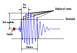
Fig. 2: A typical AE signal |
|
AE signal analysis extracts the characteristic parameters such as rise time, duration, peak amplitude,
number of counts defined in Fig. 2. This approach often gave controversial results because they lack a
physical justification of the signal features used to sort the experimental signals into different
mechanisms. This AE approach remained mainly as a qualitative technique.
The method for AE source location using triangulation technique is based on the time arrival
time difference between the first arrivals of individual AE events at different sensors.
Challenge: The time-of-flight is usually determined by presetting a threshold value.
Dispersion and attenuation can affect the arrival delay (Fig. 2). This setting can be subjective and
ambiguous in noisy environments and may lead to errors in locating the AE location. In addition, in
civil structures the direct first arrival is strongly distorted by the multiple reflections and
sometimes yields substantial errors!
The proposed Time-Reversal (T-R) for passive interrogation of evolving damage can overcome the
above drawbacks. Further, the T-R can retrieve the AE loading history, an indication of the severity
of the damage. The method reveals many distinct advantages over triangulation method.
Return to top of page
Thrust 3: Hybrid-mode Energy
Scavenger (Energy Harvesting) to Power Wireless Sensor
A truly self-sustained wireless sensing system requires sustainable energy supplies. Existing harvesters generate too little power, require very high operating frequencies, and have too narrow system bandwidths. These limitations have made them ineffective and inefficient, especially for bridges. The power density of current state-of-the-art miniature air flow turbines is listed as follows.
Table 1: Summary of current state-of-the-art miniature air flow turbines
| Author(s) |
Year of
publication |
Number of
blades |
Tip diameter
(cm) |
Speed
(m/s) |
Efficiency |
Power
density
(µW/cm2) |
| Federspiel |
2003 |
4 |
6.4 |
5.1 |
11% |
0.87 |
| Holmes |
2004 |
24 |
1.2 |
40 |
10% |
0.88 |
| Myers et al. |
2007 |
12 |
12.7 |
4.4 |
7.7% |
0.04 |
Challenge: A hybrid-mode energy harvester utilizing wind power from MWT and solar energy will be designed to power the wireless sensors for on-board signal processing and wireless communication among wireless sensors.
Return to top of page
| |
 |
| |
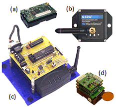
Fig. 4: Wireless sensors: (a) Crossbow Mote; (b) MicroStrain G-Link; (c) WiMMS (U. Michigan); (d) WISP (NCSU). |
Thrust 4: Multi-media Wireless Smart Sensor (Wireless sensing)
Various wireless sensor prototypes and platforms have emerged for monitoring structures (Fig. 4).
Among the existing wireless sensors listed in Table 2, none of the wireless smart sensors is capable of performing on-board AE diagnostics.
Table 2: Summary of representative wireless sensors
| |
Mote, 2003
Crossbow |
G-Link, 2008
MicroStrain |
WiMMS, 2004
(Lynch et al.) |
WISP, 2008
(Liu and Yuan) |
Highlighted
Features |
Open hardware
architecture; OS
software library |
±10g tri-axial
acceleration;
Lithium battery |
16-bit ADC,
computational
32-bit core |
Active, parallel
processing; 20
MHz sampling |
| Microprocessor(s) |
Atmega128 |
|
8-bit AT8515
32-bit PowerPC |
AVR/FPGA
AT94K10 |
| Sensing interface |
Extendable |
Accelerometer |
Accelerometer |
Piezoelectric;
Extendable |
| Dimension (mm) |
60× 35 × 25 |
58 × 43 × 26 |
70 × 70 × 25 |
35 × 30 × 20 |
| Power consumption* |
active: 60 mW
sleep: 75 μW |
active: 93 mW
sleep: 500 μW |
active: 385 mW
sleep: 500 μW |
active: 270 mW
sleep: 120 μW |
* Estimation only, depending on various factors, e.g. program, duty cycle, sampling rate and etc.
Challenge: A new integrated wireless smart sensor system including a self-sustained
wireless smart sensor, a hybrid-mode energy harvester and embedded diagnosis algorithms will be
designed and developed for automated AE diagnosis to detect, localize, characterize, and trace
the evolving damage.
Return to top of page
Thrust 5: Prognostics Using Bayesian Theory (Prognosis)
Diagnostics only quantify the local damage of the structural component; prognosis involves incorporating the diagnostic information into predicting the future progression of the damaged state of the structural components to failure under environmental conditions. Bayesian updating allows the use of dynamic diagnostic information with prior knowledge for improved prognosis.
Challenge 1: Reliability of the current RUL prediction models is very low. Primary method for bridge condition assessment is qualitative based on visual observations. Differences between theoretically calculated and observed life prediction may differ by an order of magnitude. In BMS, the rating used to describe the various possible environments for a bridge element are neither accurately defined nor linked to the NDE inspection results affecting the element deterioration. The quality of the inspection and condition rating input is subjective (visual inspection based on the inspector’s view) and time delayed due to inspection cycles (every two years or longer).
Challenge 2: The RUL prediction requires structural model. Currently the physics-based RUL is limited to the prediction on the material level, such as using the Paris law in simple coupons. Probabilistic deterioration model that incorporates the structural information and failure model naturally will lead to more accurate RUL prediction. The ISHM system will use the local damage data to predict the RUL at the structural component level.
Thrust 1 | Thrust 2 | Thrust 3 | Thrust 4 | Thrust 5
Top of Page
|